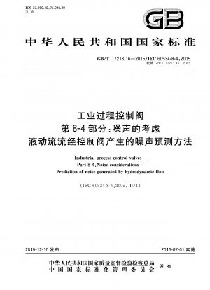
GB/T 17213.16-2015
Industrial process control valves - Part 8-4: Noise considerations Noise prediction method for hydraulic flow through control valves (English Version)
- Standard No.
- GB/T 17213.16-2015
- Language
- Chinese, Available in English version
- Release Date
- 2016
- Published By
- General Administration of Quality Supervision, Inspection and Quarantine of the People‘s Republic of China
- Latest
- GB/T 17213.16-2015
- Replace
- GB/T 17213.16-2005
- Scope
- This part of GB/T 17213 specifies methods for predicting the noise generated by hydrodynamic flow through a control valve and for measuring the noise level downstream of the control valve and outside the pipeline. Noise will be generated by the rapid flow in the pipeline or the cavitation phenomenon of the liquid in the slurry. This part is considered from the perspective of acoustics, fluid dynamics and mechanics, and is mainly verified by experimental data. Noise generated by sparkle is not considered in this section. The formula for calculating the propagation loss (TZL) is mainly based on the analysis of the interaction between the acoustic wave in the pipe and the coincident frequency of the pipe wall. The wall thickness tolerance of commonly used pipes should be recorded, and the allowable variation range of wall thickness tolerance will be relatively large. This section assumes an ideal straight pipe section. This section applies to all traditional control slurry types, such as ball valves, butterfly flash, sleeve simple valves, eccentric rotary valves and modified wide core ball valves. The test is currently only possible through water; the applicability of this method to fluids other than water is unknown. This part only considers the noise generated by hydrodynamic turbulence and liquid cavitation, and does not consider the noise caused by mechanical vibration, unstable flow state and unpredictable behavior. During a typical installation, very little noise will pass through the body wall. The noise measurement is mainly carried out at the standard measurement point 1 m downstream of the control valve and 1 m away from the outer surface of the pipeline. The prediction method has been verified by experimental data with water as the medium, the maximum population pressure is 15 bar, and it covers more than 90% of the known valve types. Except for the case where zf-zzz±0.1 [zs is calculated according to formula (3a) and formula (3b)], the accuracy of this method is within the range of ±5 dB(A).
GB/T 17213.16-2015 Referenced Document
- IEC 60534-1 Industrial-process control valves - Part 1: Control valve terminology and general considerations*, 2023-05-23 Update
- IEC 60534-8-2 Industrial-process control valves - Part 8-2: Noise considerations - Laboratory measurement of noise generated by hydrodynamic flow through control valves
- IEC 60534-8-3 Industrial-process control valves - Part 8-3: Noise considerations - Control valve aerodynamic noise prediction method
GB/T 17213.16-2015 history
- 2016 GB/T 17213.16-2015 Industrial process control valves - Part 8-4: Noise considerations Noise prediction method for hydraulic flow through control valves
- 2005 GB/T 17213.16-2005 Industrial-process control valves.Part 8-4: Noise considerations.Prediction of noise generated by hydrodynamic flow

GB/T 17213.16-2015 -All Parts
GB/T 17213.1-2015 Industrial process control valves - Part 1: Terminology and general principles for control valves
GB/T 17213.10-2015 Industrial-process control valves.Part 2-4:Flow capacity.Inherent flow characteristics and rangeability
GB/T 17213.11-2005 Industrial-process control valves.Part 3-2: Dimensions.Face to face dimensions for rotary control valves except butterfly valves
GB/T 17213.12-2005 Industrial-process control valves.Part 3-3: Dimensions.End-to-end dimensions for buttweld,two-way,globe-type,straight pattern control valves
GB/T 17213.13-2005 Industrial-process control valves.Part 6-2: Mounting details for attachment of positioners to control valves.Positioner mounting on linear actuators
GB/T 17213.14-2018 Industrial-process control valves—Part 8-2: Noise considerations—Laboratory measurement of noise generated by hydrodynamic flow through control valves
GB/T 17213.15-2017 Industrial-process control valves—Part 8-3: Noise considerations—Control valve aerodynamic noise prediction method
GB/T 17213.16-2015 Industrial process control valves - Part 8-4: Noise considerations Noise prediction method for hydraulic flow through control valves
GB/T 17213.17-2010 Industrial-Process control valves.Part 2-5:Flow capacity.Sizing equations for fluid flow through multistage control valves with interstage recovery
GB/T 17213.18-2015 Industrial-process control valves.Part 9:Test procedure for response measurements from step inputs
GB/T 17213.2-2017 Industrial-process control valves—Part 2-1: Flow capacity—Sizing equations for fluid flow under installed conditions
GB/T 17213.3-2005 Industrial-process control valves.Part 3-1:Dimensions.Face-to-face dimensions for flanged,two-way,globe-type,straight pattern and center-to-face dimensions for flanged,two-way,globe-type,angle pattern control valves
GB/T 17213.4-2015 Industrial process control valves - Part 4: Inspection and routine tests
GB/T 17213.5-2008 Industrial-process control valves. Part 5:Marking
GB/T 17213.6-2005 Industrial-process control valves.Part 6-1: Mounting details for attachment of positioners to control valves.Positioner mounting on linear actuators
GB/T 17213.7-2017 Industrial-process control valves—Part 7: Control valve data sheet
GB/T 17213.8-2015 Industrial process control valves - Part 8-1: Noise considerations for laboratory measurements of noise generated by aerodynamic flow through control valves
GB/T 17213.9-2005 Industrial-process control valves.Part 2-3: Flow capacity.Test procedures